Verification of Heat-Transfer Effect: Experiment Method
To verify the heat-transfer effect of the high thermal conductive resin, we performed an experiment to compare the heat-transfer properties of conventional materials (PC+GF30%) and those of high thermal conductive resin.
- Materials
- PC+GF30wt% material (thermal conductivity: 0.3W/m/K)
- High thermal conductive polycarbonate TPN1122
(Thermal conductivity: 8.3W/m/K)
- Test piece: 100mm x 100m x 3mmt flat plate
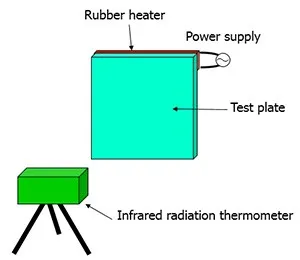
- Measuring conditions: 3.2W of power from test piece transferred to a rubber heater A portion of the test piece was heated, and the change in temperature was measured using an infrared radiation temperature measuring device.
Verification of Heat-Transfer Effect: Experiment Results
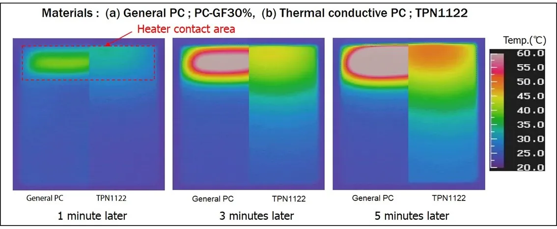
With the conventional material, the temperature rose only at the area in contact with the heater, and no heat was transferred elsewhere.
The experiment confirmed that the high thermal conductive resin transferred heat well to areas other than the area in contact with the heater.
The following effects can be expected from the use of high thermal conductive resin.
- Preventing high temperatures in specific areas
→ Preventing burns - Uniform temperature distribution
→ Reduced warpage - Increase in the area of the high-temperature section
→ Increase in the amount of heat dissipated through heat transfer
Thermal Conductivity Anisotropy
Thermal Conductivity Measurements for Molded Plates of Representative Grade
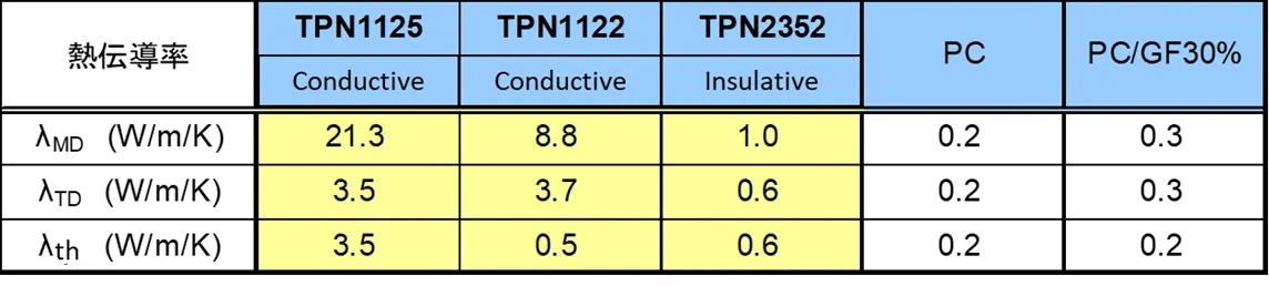
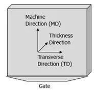
Due to the effect of the orientation of the filler, thermal conductivity is highest in the machine direction, and the thermal conductivity in the thickness direction is not very high.
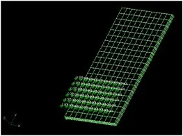
Effect of Thermal Conductivity in Thickness Direction: CAE Analysis Conditions
The thermal conductivity of this material is not as high in the vertical (thickness) direction as in the planar direction.
Due to concerns that this may cause issues during practical use, CAE analysis was used to
compare the heat-transfer properties of anisotropic resin, which has low thermal conductivity in the thickness
direction, with isotropic resin.
Software used for analysis: CAEFEM v8.3
- Analysis conditions:
-
- Model shape:
- 100 x 50 x 3mm flat plate
- Analysis model:
- Hexahedral quadratic element 20 x 10 x 3 mesh
- Boundary conditions:
- Heat flux of 0.001W/mm2 applied to surface of 30mm edge
- Initial temperature:
- 20°C
- Material constants
-
- Anisotropic body: λx= 8W/m/K λy= 8W/m/K
λz = 0.4W/m/K (thermal conductivity 1/20th only in thickness direction)
C = 0.14J/g/K r = 1.2e-3g/mm3 - Isotropic body: λx = 8W/m/K λy = 8W/m/K
λz= 8W/m/K C=0.14J/g/K r= 1.2e-3g/mm3
- Anisotropic body: λx= 8W/m/K λy= 8W/m/K
Effect of Thermal Conductivity in Thickness Direction: CAE Analysis Results
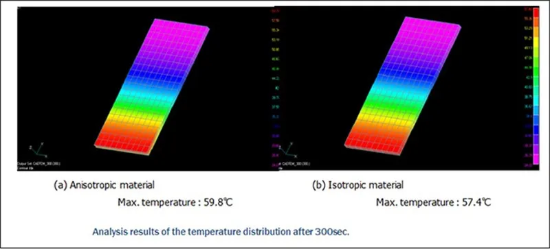
Under these conditions, the analytical results show that the temperature distributions of the anisotropic material (thermal conductivity in the thickness direction is 1/20th that in the planar direction) and the isotropic material are nearly equal.
We believe that anisotropic materials with low thermal conductivity in the thickness direction, such as the material in question, have no practical issues.